Tutorial: Creating a sphere with SALOME
This tutorial is aimed at familiarizing you with SALOME, and how to use it to create a geometry for simulation in FDTD++. The spherical particle used in the sphere in the tutorial Scattering by a dielectric sphere.
You will learn:
- Basic operations in SALOME (the interface, modules, primitive shapes, etc.)
- How to create primitive geometries, meshes, and groups
- How to create a single body, consisting of a single material, for FDTD++
Contents
Tutorial
Starting SALOME
The first step is to (obviously) start SALOME. The screen should look like the following:
Create the geometry
Our first (real) task is to create the geometry. Note the Module toolbar near the top of the screen. This allows you to switch between SALOME operations (geometry creation, meshing, etc.). Click the Geometry module (circled in red, in the following image). This should activate the Activate module dialogue, as shown in the following image. Click New.
Next, notice the Primitives toolbar (circled in red, in the following image). This allows you to create a variety of primitive shapes. Click the the Create a sphere button (circled in red, in the following image). This should activate the Sphere Construction dialogue, as shown in the following image. Change the Radius to 10 (the geom scale parameter will be used to scale this in FDTD++). Click Apply and Close, and the sphere is created.
Create the volume group
Now that the geometry has been created, the next step is to create something called a group. This concept will become more clear below, when we use it to assign material properties to the sphere. Select the sphere that was created above in the Object Browser (circled in red, in the following image). Create a Group for the sphere (this will designate the material properties), by going to New Entity $\rightarrow$ Group $\rightarrow$ Create Group.
In the Create Group dialogue, first select the volume as the Shape Type, as shown in the following image. Then, click Select All. Finally, click Apply and Close.
The next task is to create the mesh that can be read by FDTD++. Activate the mesh module (circled in red, in the following image). The screen should like like the following:
Create the mesh
Select the sphere that was created above in the Object Browser. Go to Mesh $\rightarrow$ Create Mesh. See the following image.
In the Create mesh dialogue, click on Assign a set of hypotheses. On the Create mesh dialogue, click on 3D: Automatic Tetrahedralization. See the following image.
In the Hypothesis Construction dialogue, accept the default settings by clicking OK. See the following image.
Click Apply and Close in the Create mesh dialogue. Ensure that Mesh_1 is selected in the Object Browser. Then, go to Mesh $\rightarrow$ Compute. See the following image.
This should activate the Mesh computation succeed dialogue, as shown in the following image. Click Close.
Create the mesh group
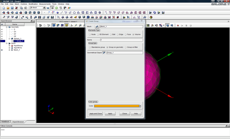
The next task is to assign material properties, to be read by FDTD++, to the elements of the mesh just created. Select Mesh_1 in the Object Browser. Then, go to Mesh $\rightarrow$ Create Group, as shown in the following image.
In the Create Group dialogue, first select Volume as the Elements Type (circled in red, in the following image). Then, in the Name box (also circled in red), the name needs to be changed to 1, where the 1 will correspond to material 1 in the materials file (e.g., for a material with unique integer of 2 in the materials file, the name would be 2). Next, click Group on geometry in the Group type (also circled in red). Next, click the arrow next to Geometrical Object. This should activate a drop-down menu, as shown in the following image. Click on Direct geometry selection. See the following image.
Then, in the Object Browser, click on Group_1 under Sphere_1, as shown in the following image. Click Apply and Close.
Export the mesh
Now that the geometry has been created, the mesh has been generated, and the material properties have been assigned, the final step is to export the it in the *.unv format that can be read by FDTD++. Ensure that Mesh_1 is selected in the Object Browser. Then, go to File $\rightarrow$ Export $\rightarrow$ UNV file. See the following image.
In the Export mesh dialogue, save the file to your work directory.


